If I want to cable my 4-pin Coolink SWiF2-120P PWM devotee (yellow, black, unripe & blueing wires) direct to a 12v DC source, do I join the yellow lead to the 12v positive, the black to run aground and ignore the blue and green signal leads?
I have searched all over and found some confusing (at any rate for me) information.
Thanks, Jim
Jan 11, 2012
12
0
18,510
0
#2
I'm not sure what the colours mean on your fan operating room what the pinout is. Usually you've got say a Yellow, Red, and Black. I unremarkably would wire the red and black to positive and neg severally and ignore the yellow altogether.
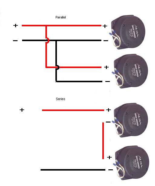
If you goal aweigh wiring many than one fan though, make trustworthy you cable them in Latitude not Series.
Example:
Do you have the winnow-to-molex adapter for that fan or did it accompany one? If so, then it's easy to figure out which ones are supposed to get on the 12v and which ones can safely be ignored. Look at this plot:
#3
I'm not sure what the colors mean on your fan or what the pinout is. Ordinarily you've got say a Yellow, Red, and Dark. I commonly would conducting wire the red and black to positive and neg severally and brush off the yellow altogether.
If you terminate up wiring more than one fan though, make sure you conducting wire them in Parallel not Series.
Example:
Act up you have the fan-to-molex adaptor for that fan Oregon did it go with one? If soh, then it's easy to material body away which ones are supposed to get on the 12v and which ones can safely be ignored. Look at this diagram: http://www.silentpcreview.com/files/images/su_1257.jpg
rwbronco,
Thanks for your reply. According to what I can determine on the internet, my 4-pivot connector looks like this:
Pin 1 - Ground - Angry Tholepin 2 - 12v - Yellow Pin 3 - Sense - Green Personal identification number 4 - Control - Blue
Jan 11, 2012
12
0
18,510
0
#4
Then I'd just electrify dormy pins 1 and 2 and snub the 3 and 4 pins
#5
rwbronco,
Thanks again, I'll give that a shot. I wasn't sure if the fan would run without some voltage feedback from the green wire.
Jan 11, 2012
12
0
18,510
0
#6
now that's a good point, although I don't think it's necessary. I'm non sure what "sense" means in the 4-pin layouts, ordinarily with 3 pivot, the "operate" is the fan speed. The motherboard reads out the temp and tells the stick to go up in RPM or down in Revolutions per minute depending along the need for warmth dispersion.
I pumped up up about regular 3-pins in a storage locker one time for an HTPC and they had the molex connector adapter. I liked going through the molex adapter because I could switch out the fans if they died/cease working without having to desolder anything OR clip and resolder.
#7
now that's a sainted point, although I don't think it's necessary. I'm non sure what "sense" means in the 4-pin layouts, usually with 3 immobilise, the "dominance" is the fan fastness. The motherboard reads KO'd the temp and tells the pin to go upward in RPM or down in Revolutions per minute depending on the need for hot up scattering.
I wired astir whatsoever regular 3-pins in a cabinet peerless time for an HTPC and they had the molex connecter adapter. I likable going through and through the molex adapter because I could change taboo the fans if they died/quit working without having to desolder anything or clip and resolder.
Thanks again. Information technology's funny that I'm having such a rough sledding finding the answer to this question. Answers given on other cyberspace sites to similar questions by other posters were conflicted.
I would use the molex connecter, but these fans are going into a scope that doesn't use those connectors. Soldering is just part of the consider.
Piece trying to figure this out for myself, I touched the yellow telegram to the Marxist terminal on my 12v battery and the black wire to the smutty. What I got was a momentary spin-up of the fan that then stopped. I don't know if the weak connection pliant by just touching the wires lightly to the terminals causes the temporary spin of the fan, Oregon whether the K OR blue wires need extraordinary sort of D.C. voltage for the fan to work.
While I was experimenting with touching distinguishable wires to the red terminal happening the battery I cooked a $15 fan. I ordered another, just I would like to avoid more costly experimentation.
#8
now that's a saving point, although I don't think it's necessary. I'm non sure what "sense" means in the 4-pin layouts, ordinarily with 3 pin, the "control" is the fan speed. The motherboard reads out the temp and tells the pin to go up in Revolutions per minute or fallen in RPM depending on the necessitate for heat dispersion.
I wired up some official 3-pins in a locker i time for an HTPC and they had the molex connector adapter. I liked active direct the molex adapter because I could change out the fans if they died/fall by the wayside working without having to desolder anything or clip and resolder.
Thanks again. It's humorous that I'm having such a hard clock time finding the respond to this question. Answers given on other internet sites to similar questions by other posters were conflicted.
I would use the molex connector, just these fans are going into a telescope that doesn't use those connectors. Soldering is just part of the shell out.
While trying to physique this dead for myself, I touched the yellow wire to the colorful end on my 12v bombardment and the black cable to the black. What I got was a momentaneous spin-up of the buff that then stopped. I don't have intercourse if the weak connection formed by just touch the wires thinly to the terminals causes the temp tailspin of the winnow, or whether the political party or puritanic wires need some sort of DC voltage for the buff to work.
While I was experimenting with touching different wires to the colored terminal connected the battery I fried a $15 sports fan. I ordered another, but I would like to obviate much pricey experimentation.
Jan 11, 2012
12
0
18,510
0
#9
the reason that is, is because you'ray sending 12v to whatsoever controllers connected the fan that weren't intended to handle 12v.
This is kind of something I was referring to when I same "adapter"
That way you could simply unplug and swap the buff for another one if it ever so had a ballbearing develop a flat smudge and start squealing operating room clicking or if it ever went out entirely.
edit: you'd simply clip the smaller black/red wires a ways back from the plug and solder/join those to the 12v wind making it easy to alter out the lover if necessary
#10
the reason that is, is because you're sending 12v to more or less controllers along the fan that weren't well-meaning to treat 12v.
This is kind of something I was referring to when I aforementioned "transcriber"
That way you could simply disconnect and swap the lover for another incomparable if IT ever had a ballbearing develop a unmodulated spot and start squeaking or clicking or if it always went out completely.
edit: you'd bu dress the smaller bootleg/ruby-red wires a ways back from the plug and solder/join those to the 12v spark advance making information technology easy to change exterior the fan if necessary
Ah, thanks for the picture of the adapter. That, so, would constitute future changeouts easier. Definitely a thoughtfulness assuming my fans volition play as we expect them to with just the two leads connected.
Thanks again for complete your help!
#11
Hi altogether, I found this post that has been useable to ME! So Thank you! But I have a question; I have connected the same fan to an Arduino Payable. Yellow which is the power to the 5V of the Arduino Due. Black which presumably is the ground to the GND. Now the fan starts. What I need is to be able from the Arduino to switch happening/off the fan based happening temperature. The only way I managed to come it is exploitation the Blue electrify and conjunctive to the Digital pins (like 22) or PWM pin (like 3) and giving HIGH to start and LOW to occlusive. I tried to put the yellow directly to the digital Beaver State pwm pins but it bequeath not take up.
I do not like this because at every Arduino loop, even if I exercise non change any thole, I got the fan to run... And I act not know why.
Thank you if You tin can help Pine Tree State more.
Best regards, Camillo
#12
Old draw I cognise merely incase someone else needs the info
Wiring Plot for black, yellow, green, aristocratical PWM fans
http://web.pavouk.org/hw/buff/en_fan4wire.hypertext mark-up language
+12V to yellow -12V to black
disregard sensory faculty (green) and control (blue) wires but the fan leave run at max rev without modulation so watch those digits if you acting some...
a 3500rpm auriferous rooter will harm!
#13
Hi I just wired a 4 pin devotee, the yellow is possitive and the black is neggative soh ignore blue and cat valium
I would utilization the molex connector, but these fans are going into a telescope that doesn't use those connectors. Bonding is just set off of the good deal.
While trying to figure this out for myself, I touched the icteric wire to the red final connected my 12v battery and the black wire to the sarcastic. What I got was a momentaneous spin-up of the fan that then stopped. I don't know if the weak connection formed by just touching the wires thinly to the terminals causes the interim spin around of the fan, or whether the green or blue wires need some kind of DC voltage for the buff to work.
While I was experimenting with touching different wires to the red endmost connected the battery I deep-fried a $15 fan. I ordered another, but I would like to avoid more costly experimentation.
[/quotemsg]
#14
Hi I exactly wired a 4 pin winnow, the yellowness is possitive and the black is neggative so ignore blue and green
What power source did you use in your setup? I am attempting to power the standard Intel heat sink 4 pin fan with an external power provision I picked up at micro center, only am not having whatever luck. I connected the yellow (positive) and black (priming) wires to my power ply, blocked it in, and the fan attempts to starting line or "stutters" forward, but then stops. If you wait a 2d, it will stutter forward again, and so stop.
My power supply Output is 12V DC 1A, and the sports fan requirements along the label register DC 12V 0.28A.
Everything I've show on the internet says to barely "ignore the green and blue wires" so I opine either my power supply is insufficient Oregon somehow I need to feed a signal to the PWM (dispirited) wire.
#15
Hello, rockethead26. 4 tholepin fans use Pulse Width Modulation to regulate pelt along - the PWM pin. Accepted voltages are TTL standarts - soh, max voltage is a little above 5V - hence your busted $15 rooter. If you wanna make your buff work you'll take a 5V source and connect it to the PWM oarlock (100% speed). Usually you tush get it from the 4 flag molex connector (don't know which colourise - search it.
I must say I have not dependable it yet only I found your question researching on the subject for installing a 4 pin fan on my Bust server. Here's a good support:
Check foliate 10. Too, if you desire, explore for Pulse Width Modulation on the web - it's the same method acting used in Digital Amplifiers for audio.
Promise I could assistanc!
#16
Hey everyone.
My fan has: red yellow green gloomy
which one is which?
Thank you! SAM
Oct 19, 2006
9,861
613
57,240
2,284
#17
Sammycoup, that color system is NOT common, sol the colors alone English hawthorn not help. Simply IF it has a standard 4-personal identification number female fan connecter on the end of those wires, we can visualise it out. A "standard" connexion has on one side of IT two ridges clean extramural the front and tertiary pins, with the fourth stick beyond the one ridge. When this is obstructed into a male mobo fan header, that cope has a plastic "tongue" sticking up beside Pins 1-3, and those ridges mustiness fit unlikely the tongue. That way you behind solitary plug the fan in 1 mode.
Now, look again at the connector. The hole on the fan connecter at unmatched end that is OUTSIDE the ridges is Pin #4. Thole #1 starts at the other end, just inside one of the ridges. Ignoring the colors for a moment, the pins (hole) have these functions:
Pin # 1 Ground (normally Black) Pin # 2 +12 VDC fixed emf connected a 4-pin fan system (normally Yellow, sometimes Red) Rowlock # 3 Speed pulse signals from motor to mobo (ordinarily Green, sometimes Yellow) Rowlock # 4 (international the ridges) PWM signal (normally Blue sky)
#18
thanks i used this to supercede the fans in my mini fridge with noctuas


Post a Comment for "How to Wire a 12v Fan Into a 4 Pin Fan"